


Expertise

From the early pioneers on the Snowy Mountains Hydroelectric Scheme, to our leaders and innovators of today, our people make us who we are.
Through our network of global specialists and by collaborating with local partners, we connect you with the best teams and capabilities to deliver highly innovative and sustainable solutions.
As an organisation we are continually evaluating ways we can better provide a safe, flexible, inclusive and respectful workplace for our people and clients.
People are at the heart of our organisation, we strive to create a flexible, diverse and inclusive environment that enables our people to thrive to their fullest potential.
Explore career opportunities
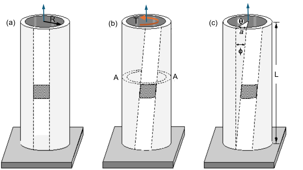
Torsion occurs when an element twists due to opposing torque forces applied at each end. This twisting creates shear stress at a perpendicular section. The torque results in an angle of shear (ϕ), and in a section perpendicular to the torque axis, it results in shear stress (τ). Figure 1 illustrates the stages of torsion in a cylindrical element, showing how it deforms under torque force, from an unloaded state to the application of torque, and the resulting twist.
The primary cause of torsional demand in intake towers is earthquake loading, though other factors like strong waves can also induce significant torque forces. According to the USACE Engineering Manual for Structural Design and Evaluation of Outlet Works (2003), torsional effects can be neglected if the mass and stiffness distribution around the tower’s axes is symmetric. Symmetry is defined by an eccentricity — the distance between the center of mass and the center of rigidity — that is no greater than 10% of the tower’s width. When this condition is met, it is possible to design or evaluate intake towers for bending moments and shear using two-dimensional beam models or time-history analyses.
Figure 2 illustrates some common sources of eccentricity in intake towers that contribute to torsional demand. These sources include:
These sources of asymmetry increase the potential for torsional actions in the structure.

Torsional demand at a given cross-section of the tower arises from all the torsional moments above that section. In the case of earthquake loading, the seismic torsional moment is calculated by multiplying the mass of the tower by seismic acceleration and its eccentricity. This torsional moment is taken by the shear-resisting elements (e.g., reinforced concrete walls) based on their stiffness. Figure 3 shows how seismic torsional moments are applied separately from the tower’s and access bridge’s masses.

For example, the torsional moment due to the tower’s asymmetry is calculated by multiplying the tower’s mass (Mt) by seismic acceleration (a) and its eccentricity (e). The torsional moment from the access bridge is similarly calculated by considering the mass of the bridge (Mb) and its lever arm (D). These moments lead to a shear strain (γ) and stress (τ) that the tower’s walls must resist.
Guidelines for estimating the torsional capacity of intake towers are sparse, but the ACI-318 (2019) “Building Code Requirements for Structural Concrete” offers some insight. It defines the torsional capacity of a reinforced concrete element as the combination of contributions from both concrete and reinforcement. Once the element cracks under torsion, strength is provided by closed horizontal bars, stirrups and longitudinal bars near the surface of the hollow section.
According to ACI-318, torsional moments can be ignored if they do not exceed 25% of the cracking torsional moment (Tcr), which represents the torsional capacity provided solely by the concrete. The cracking torsional moment is calculated as:
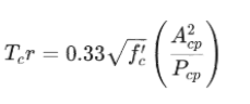
where fc′f‘_{c}fc′ is the compressive strength of the concrete, AcpA_{cp}Acp is the area enclosed by the perimeter of the concrete, and PcpP_{cp}Pcp is the perimeter of the concrete cross-section. The threshold torsion (Tth) is calculated as:

An alternative formulation is used when axial forces are significant, which may apply to intake towers.
A typical intake tower with a reinforced concrete cylindrical shaft was analysed to evaluate the impact of asymmetry, voids, and eccentric masses on torsional capacity. This tower is 36 meters tall and has seven intake ports along the upstream edge. The concrete strength is 20 MPa, with 230 MPa yield strength reinforcement at 305 mm spacing. The tower’s top houses a gantry crane and heavy equipment, which adds additional masses.
Figure 4 shows the tower and cross-sections assessed for torsion, including sections at different heights and orientations of intake ports. For each section, the cracking torsional moment (Tcr) was calculated using the previously mentioned formula. The results indicate a significant reduction in torsional capacity with the presence of intake ports. Sections with one or two intake ports show a 45-50% reduction in torsional capacity compared to a full-section model.

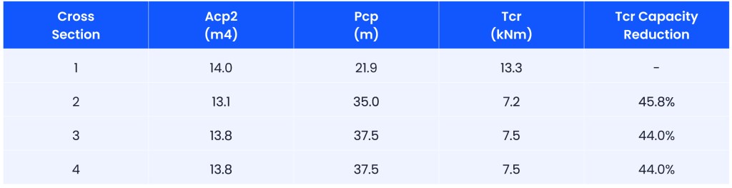
Table 1 presents the calculated cracking torsional moments (Tcr) for the analysed sections. The reduction in torsional capacity for sections with intake ports is substantial, especially for Sections 2 to 4, which are reduced by approximately 45-50%. The table also shows the torsional capacity reduction percentages for these sections.
In addition to torsional capacity, the flexural and shear capacities of the same sections were analysed using ACI-318 formulations. Table 2 presents the flexural moment (Mx, My) and shear (V) capacities for the different sections. The reduction in flexural capacity ranged from no reduction to 18%, while the shear strength reduction was negligible (up to 3.1%).
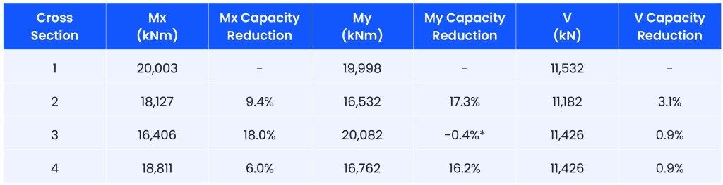
These results show that while torsional capacity is significantly affected by the presence of intake ports and voids, flexural and shear capacities are relatively less sensitive. The reduction in flexural capacity ranged from minor to 18%, and the shear strength reduction was minimal. This highlights the critical importance of addressing torsional behaviour in intake towers, especially considering its sensitivity to structural asymmetries.
In conclusion, torsion should not be neglected in the design of intake towers, as its impact on torsional capacity is much more significant than the effects of bending and shear actions. When designing or assessing intake towers, engineers must consider the potential sources of torsional demand, such as voids and eccentric masses, and account for their influence on both torsional demand and capacity. Proper evaluation of torsional effects will help ensure the safety and resilience of intake towers under seismic loading.

Francisco Lopez
Chief Technical Principal – Concrete Dams
Francisco has over 25 years of experience in dams, seismic, and structural engineering. He has led a team of more than 150 dam professionals across Australia, New Zealand, the Philippines, Chile, the United Kingdom, the Middle East, the USA, and Canada. Recognised both nationally and internationally in the dams industry, he is a member of technical committees for the International Commission on Large Dams (ICOLD), the Australian National Commission on Large Dams (ANCOLD), and the US Society on Dams (USSD). He also contributes to working groups responsible for developing technical guidelines and industry standards and is a frequent author of technical papers and magazine articles presented and published at national and international levels.
Dr. Monte Azmi, Senior Associate Engineer – Water Resources at SMEC, has published a paper in the Journal of Natural Hazards, focusing on enhancing estimations of crucial dam breach parameters such as peak discharge, breach formation time, and average breach width. This research is pivotal for understanding and mitigating the impacts of dam failures.
Reflecting on my recent participation in the US Society on Dams (USSD) Conference held in Seattle, USA, from 22 to 25 April 2024, I am energised by the wealth of knowledge exchanged and the collaborative opportunities that emerged.
"The water and hydropower sectors have changed dramatically since our origins on the iconic Snowy Mountains Hydro Scheme 70 years ago in 1949, one of the largest and most complex hydroelectric schemes in the world. While technology has advanced rapidly, water is and will continue to be an essential and ever scarcer global resource."


