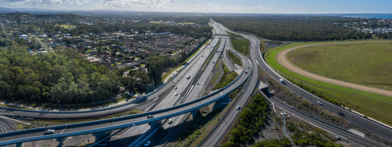
The widenings are intended to be constructed between 2023 and 2026 and will be about 40 years younger than the original bridge. Most of the creep and shrinkage of the existing bridges has therefore already occurred. The new bridges have yet to be constructed and creep and shrinkage will be limited to the construction phase. This differential creep and shrinkage will cause the two bridge decks to shorten at dif- ferent rates. This is problematic when trying to join the two decks together. This paper investigates the possibility of connecting the two decks via a cast in situ concrete slab.
It was expected that the new deck, if unrestrained, would shorten significantly more than the existing deck. The slab would restrain this shortening, developing tensile stresses. The concern was that these tensile stresses would lead to unacceptable cracking and durability issues in the long term. The design process involved calculating the relative shortening from creep and shrinkage and then applying this movement to a FEM model. The stresses in the decks and slab could then be evaluated.
Analysis and Design
Creep and shrinkage curves were calculated for both the new and existing bridges in accordance with the CEB-FIP (1990) Model code. The applied loading was obtained by first calculating the differential strain between the two decks due to creep and shrinkage.
Four months are allowed after the new deck was complete to allow the maximum amount of creep and shrinkage to take place. A total of 250 days was allowed after the average construction of a deck segment and prior to connecting the decks together. Table 1 indicates the equivalent differential creep and shrinkage between the two decks.
Table 1. Differential Creep and shrinkage values for Umhlatuzana River Bridge widening
The resultant creep strain was calculated as 150 µε (0.93 x 5 MPa/31 GPa) and the shrinkage strain as 159 µε. The resultant effective creep and shrinkage strain from 250 days to 36500 days was therefore 309 µε.
A Robot FEM model was set up with girders modelled as beams and with a slab joining them via rigid links. Robot does not have a feature to model the effect of creep and shrinkage. To overcome this short- coming, an equivalent temperature load was applied.
Results and Discussion
Deck Movement and Forces
The expected movement of the unrestrained deck due to creep and shrinkage based on an equivalent temperature load is 64 mm. The model shows that the movement in the new deck is 31 mm and the existing deck is 28 mm, a difference of 3 mm. It makes sense that the new deck would shorten more than the existing and its of interest that the existing decks shortening is almost the same as the new. Another point of interest is that if the movements of both decks are added together then the total movement is similar to the unrestrained movement from creep and shrinkage.
The movement indicates that the new deck is restrained by the existing deck. Effectively the new deck induces compression into the existing deck and slab. The compression in the existing deck in turn restrains the new deck, resulting in the new deck undergoing tension. It was therefore important that this effect was considered in the deck design model.
Compression is generally favourable and the additional compression in the existing deck was therefore not considered problematic. The new deck however needed to account for the reduction in axial load. Furthermore, an added benefit from joining the two decks monolithically and the reduced movement was that smaller expansion joints could be used.
Deck stresses
For most of the deck, excluding the ends, the compressive stress in the longitudinal direction is 3.65 MPa with a negligible stress in the transverse direction. This compressive stress is not considered excessive. The deck can accommodate a stress of 0.4 fcu which is a peak stress of 16 MPa. The stresses caused by differential creep and shrinkage are therefore well within the capacity of the slab.
In the last 15 m of the deck, the longitudinal compressive stress increased and peaked at 10 MPa which is within the required limit. The tensile stress’ are however above the limit with tensile stresses up to 7 MPa.
To decrease the high tensile stresses, the thickness of the connecting slab is increased, over a length of 15 meters, to a depth of 1 m. The increased depth results in a larger area over which the load is applied, which results in the stress magnitudes decreasing. The deck is also prestressed transversely so that a 5 MPa stress is added to the section. Figure 2 shows the principle stress 1 after prestressing and thickening of the slab.

Figure 2 indicates a decrease in tensile stress magnitude throughout the 15m long thickened slab. Most of the thickened slab is in compression with stress values ranging between 0.13 and 3.75 MPa. However, the first 5 m of the slab remains in tension, but the magnitudes of the stresses are below the tensile strength limit of 2.9 MPa.
The compressive stresses have increased in magnitude to values ranging between 3.00 to 5.50 MPa which are within acceptable limits.
Conclusions and Recommendations
This paper investigated connecting a new box girder deck of 414 m to an existing one. The following key conclusions are made:
- Differential creep and shrinkage plays a major role as the two decks shorten at different rates when the stitch slab is cast;
- Delaying the connection of the decks once the prestressing is installed reduces the differential movement substantially;
- The overall movement of the decks reduced which allowed for smaller expansion joints;
- The analysis indicated that most of the stitch slab is in compression (3-4 MPa) which is easily accommodated by the deck concrete as concrete is strong in compression; and
- High tensile stresses (15 MPa) were evident at the deck ends leading to impractical amounts of reinforcement;
- The previous noted issue was resolved by increasing the thickness of the slab at the deck ends to 1 m depth and prestressing transversely;
- This action reduced the tensile stresses in the stitch slab to below the tensile cracking limit (2.7 MPa) of the concrete. The compressive stress increased but was also within the compressive limit (0.4 fcu) of the concrete.
In summary, the analysis showed that connecting two 413 m decks monolithically is possible.
 Engineering positive change: delivering community-centric infrastructure in rural Africa
Across the vast and diverse landscapes of rural Africa, many communities face significant barriers to accessing essential infrastructure. Limited access to clean water, sanitation, reliable transportation, and consistent energy supply impedes daily life, and deepens existing inequalities.
 A Sustainable Approach to Reservoir Management: Advanced Sediment Yield Forecasting Using SWAT
Reservoir sedimentation is a growing concern for water resource managers and hydropower projects, as it diminishes water storage capacity, affects water quality and poses long-term challenges for operational efficiency.


